|
I bought a SONY®™ MPF Floppy Drive many years back from a store called "FRY'S ELECTRONICS" paying $29.95 US(+TAX), and installed it in my computer. Since my 34-pin FDD logic cable was keyless, meaning it could be plugged into the drive two different ways (only one way is right!), I carefully figured out how to connect it correctly by noting where the missing pin was located (this will be explained below). Everything worked fine; I was very happy with that Sony drive. After
a few years, I was given a used computer with a working but unproven
FDD in it, so I decided to use my Sony FDD in it instead. The case was
smaller, but it came with keyed logic cables. So I assumed,
as I'm sure you would too, I could rely on Sony's keyed connector
to make my task easier; after all, it can only connect one way when using
a keyed cable! Things may have turned out a better had I tried booting
up the machine with a boot diskette, but I can't be sure of that. Apparently,
the BIOS was set to boot from the HDD first. If not, I simply wasn't paying
attention to the drive light (which I now assume never flashed on during
its initial boot-up test). About 15 min. later, I decided to format a
floppy: I inserted a diskette and entered the format command, and t the
drive light turned on as expected. However, it wouldn't function
correctly and now the light wouldn't turn off! I shut down
the system and rebooted (expecting that to fix things), but the
FDD drive light came on immediately and never turned off! I
took it back to the original computer to test it there, and got the same
results! Much time was spent trying to figure out why the drive failed,
until I happened to notice that the 34-pin connector didn't look the same
as one on a TEAC®™
drive someone gave me. After examining the SONY FDD in detail (see
below), my conclusion at the time had been that the drive left the
SONY factory with a serious mistake, "dooming
it to fail" if
a keyed cable connector was plugged into it!
After contacting
SONY to see what they could do about this, I was surprised by them again:
SONY would do absolutely nothing about what certainly appeared
to be an obvious mistake on their part, because, as they
kept repeating to me, I'd bought what they called an "OEM" product
and they take no responsibility for any errors in that case! (But SEE
Update* below.) So, that's when a "SONY"
label really means "Forget You!" *UPDATE: An astute reader of this page (after finding four drives like this in his own stock!) did some research and informed me that this disgusting chain of events and still deplorable situation was due to COMPAQ Computer's decision to use FDD drives with NON-standard wiring in their boxes! But SONY should still carry some of the blame for making this despicable practice possible by agreeing to produce drives for COMPAQ. Prior to this discovery, I'd purchased many "OEM" components before, and had been under the impression that it simply meant the product wouldn't be under the same warranty from its manufacturer; never that it could internally be made completely different YET still appear exactly the same! It's my opinion that SONY should have marked these drives in some way; and that's why I hold them partly responsible. SO BEWARE any SONY OEM drives!!! What does HP do with their own and now acquired COMPAQ products? The worst case I've heard of along similar lines is that DELL Computers might use NON-standard wiring for their POWER SUPPLIES! If you purchased the most expensive power supply available as a replacement or tried using one of these DELL Supplies in some other computer, your Supply, CPU and Motherboard might all end up burnt and useless!!! This is something that's always a possibility when buying a "name brand" product. GENERIC computers, since they depend upon off-the-shelf-components from many different manufacturers, are often more compliant with any kind of common standards. So, make sure you know exactly how hardware compatible your PC is before working on it! |
|
The following detailed illustrations and comments will not only show you how SONY shipped out what I still consider to be defective FDDs, but will also help you determine how to connect your own FDDs correctly. Remember: Everything said here could apply to any SONY OEM FDD (not just the MPF 920 series) and to any other FDD manufacturer; Mitsumi made some OEM drives for COMPAQ too! |
|
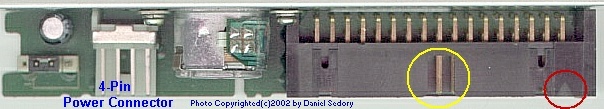
The first thing you would probably notice about the 34-pin connector is that a rectangular piece was cut out of the middle of its shell's top surface (see inside the YELLOW CIRCLE above). The cutout is supposed to match a raised rectangular block on the logic cable's connector known as a key which makes sure it can plug into the FDD only one way. However, not all floppy drive cables have a key on their connectors. | ||
| This is a 34-pin cable and connector which has a rectangular key (see inside GREEN circle) that fits into keyed 34-pin shells as shown in the picture of the SONY FDD above. Pin 1 of this cable (red stripe) will always be on the far right side when the key is on top of the connector. | 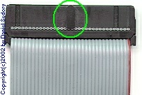 |
|
|
It's also a standard
practice for the 34-pin shells to use a small triangle (or arrowhead)
to indicate the location of Pin 1
(see inside the RED CIRCLE above). BUT,
as you will soon see for yourself, SONY used
a NON-STANDARD type of connector on this FDD !! Both
the cutout and the arrowhead in the shell
of this connector are in the wrong
place for this FDD. Plugging a floppy drive cable with a
keyed connector into this SONY FDD, rather than protecting
it from harm, will
cause it to fail! |
||
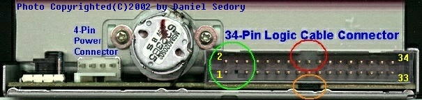
| Another standard practice for most FDDs, is that pin 3 of the 34-pin connector should be missing (so another key stuck inside the logic cable's pin 3 would be able to fit in the empty space). Unfortunately, cable manufacturers leave the installation of this little key up to their customers, and I've never seen one inside a computer! If one had been in the cable I used, it would have kept it from ever plugging into this SONY FDD and alerted me to a problem! If I had ever thought that SONY was capable of making such a serious mistake, I would have examined the drive more closely and seen that the missing pin 3 (look at the GREEN CIRCLE in the pic above) was on the opposite side of where the arrowhead and pin 1 of the logic cable would be connected to. You can even see (in the ORANGE CIRCLE above) where there's a gap in the circuit board material for the cable's key to fit. It turns out that the missing pin is indeed pin 3 for this FDD, and that the pins are to be counted as follows (from left to right in the pic above): 1,3,5,7, etc. to 33 for the bottom row, and 2,4,6,8, etc. to 34 for the top row (pins 1, 2, 33 and 34 are labeled in the pic above). |
|
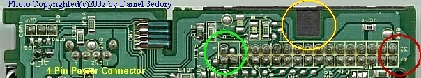
AFTER finally locating a screwdriver that fit the five small screws holding the metal shield (or bottom cover) over the SONY MPF 520's circuit board, you can clearly see the location of pins 1 and 2 marked on the board (inside the GREEN CIRCLE above). The YELLOW CIRCLE shows where the cutout in the 34-pin connector's shell should have been located... the circuit board itself having been cut away exactly where the key should slide in! Again, if I had thought SONY might have ever made large quantities of NON-STANDARD drives, I would have made sure of where the pins were located before simply plugging the cable in the ONLY way it could be !!! |
So, what happened to the Circuit Board? |
||||||||||||||||||||||||||||||||||||||||||||||||||||||||||||
|
Without having a detailed schematic of the board itself (and no help from SONY, of course!), it's difficult to determine exactly what happened. The "pinout" for a Floppy Drive's 34-pin Logic Connector is as follows ( FDC refers to the Floppy Disk Controller which is normally in a chip on the PC's Motherboard rather than a separate board now ):
When the logic cable was plugged in wrong, it connected the Ground wires from the motherboard's FDC connector to ALL of the Floppy drive's Signal pins (the even numbers), and also connected all of the drive's ground pins to the signals coming from the motherboard. My first thought was, "How could that do any damage?" But, having been in electronics for many years, I know that voltages printed on a circuit board or schematics should be considered ideal (or as you might see in some ad: 'your mileage may vary' etc.) rather than what's often found during actual testing! The voltages of HIGH and LOW logic signals vary a lot from their +5 and Zero volt ideals! The first thing I'd really need to know here is this: Were all the ground pins on the drive's 34-pin connector connected directly to its power connector's ground pin (and thus, to the power supply ground)? Or, did they get their ground reference from the connections they were supposed to have from the motherboard (FDC)? Another important question would be: Are the ground wires from the motherboard constantly grounded, or do they ever vary depending upon when/what signals are sent to the floppy drive? I'm just tossing out some questions to show that things might not be as simple as you may think. Then there's the question of whether or not the voltage level of Ground was the same in all the floppy drive's circuits, and on the motherboard; different levels could have led to this problem. "Were any of the FDC's signals capable of raising the drive's ground pins to a level higher than Ground?" I don't have any real answers here, because I don't have all the necessary facts! All I can say for certain, is that SONY MADE THIS NON-STANDARD DRIVE; and I wish I'd CHECKED EVERYTHING POSSIBLE THE DAY I BOUGHT IT!!! |
||||||||||||||||||||||||||||||||||||||||||||||||||||||||||||
The
Starman. November 18, 2002.
Revised and Updated: 24 OCT 2005.
Feel
free to copy this page and its contents to any location or media.
If you wish to contact me, use the Form
Page in the main directory.